
6.7 cummins valve adjustment sequence pdf
Valve adjustment for the 6.7 Cummins engine is a critical maintenance procedure to ensure proper engine performance and longevity. This guide outlines the detailed steps, tools, and specifications required to accurately adjust valve lash, ensuring optimal engine operation and preventing potential damage. By following the outlined sequence, you can maintain your engine’s health and performance effectively.
Understanding Valve Lash
Valve lash refers to the small clearance between the rocker arm and the valve stem tip. Properly set valve lash ensures efficient engine performance, prevents premature wear, and maintains optimal combustion. Incorrect lash can lead to issues such as noisy valves, reduced power, or engine damage. The 6.7 Cummins engine requires precise lash specifications, typically measured using a feeler gauge. Intake and exhaust valves have distinct clearance requirements, with intake often set tighter than exhaust. For example, intake valves may be set to .010″ while exhaust valves are set to .026″. These specifications can vary depending on emissions configuration and engine modifications. Measuring and adjusting valve lash accurately is crucial, as deviations can disrupt engine timing and combustion efficiency. Always ensure the engine is cold and consult the factory specifications or a repair manual for precise guidance. Regular checks and adjustments help maintain engine health and performance over time. Proper valve lash alignment is essential for smooth operation.

Preparation for Valve Adjustment
Begin by isolating the power source and ensuring the engine is cold. Remove the valve cover to access the rocker arms and valves. Gather tools like a feeler gauge and engine barring tool for precise adjustments. This step ensures safety and accessibility for accurate measurements and adjustments, preventing potential engine damage during the process.
Isolating the Power Source
Before starting the valve adjustment process, ensure the engine is turned off and all power sources are disconnected. This includes switching off the ignition and engaging the parking brake. Disconnecting the battery terminals or isolating the fuel supply may also be necessary to prevent accidental engine startup. A cold engine is required for accurate measurements, so allow the engine to cool down completely if it has been recently operated. Proper isolation ensures a safe working environment, preventing any unforeseen engine activation during the adjustment procedure. Always refer to the service manual for specific instructions on isolating power sources for your particular 6.7 Cummins engine. Safety should never be compromised during maintenance procedures. By isolating the power source, you eliminate risks of injury or damage, making the adjustment process safer and more efficient. This step is fundamental to proceeding with the valve adjustment sequence.
Removing the Valve Cover
To access the valvetrain components, the valve cover must be removed. Begin by locating the valve cover bolts, typically found along the top of the engine. Use a wrench or socket to loosen and remove these bolts in a star pattern to avoid warping the cover. Once the bolts are removed, gently pry the valve cover away from the engine, taking care not to damage the gasket or the engine surface. Place the valve cover and its gasket aside in a clean, dry location to prevent contamination or misplacement. Be cautious, as the edges of the valve cover may be sharp. Some engines may have additional clips or fasteners securing the cover, so ensure all are removed before attempting to lift it off. A torque wrench can be useful for applying even pressure while loosening bolts. Removing the valve cover provides clear access to the rocker arms and valves for the adjustment process. Always handle engine components with care to avoid damage. A clean workspace is essential for this step to ensure accurate adjustments and prevent contamination; Properly storing the valve cover and gasket will help maintain their condition for reinstallation later. This step is crucial for accessing the valvetrain and proceeding with the valve lash adjustment.
Measuring Valve Lash
Measure valve lash using a feeler gauge inserted between the rocker arm socket and crosshead. Refer to the Valve Lash Limit Chart for correct specifications to ensure accurate and precise measurements. Always measure on a cold engine for optimal results.
Using a Feeler Gauge
To accurately measure valve lash, a feeler gauge is essential. Insert the appropriate gauge between the rocker arm socket and crosshead, ensuring it fits snugly without forcing. This method provides precise clearance readings, crucial for maintaining proper engine performance. Always refer to the Valve Lash Limit Chart for correct specifications. For a 6.7 Cummins engine, typical intake lash is around 0.010″ and exhaust lash around 0.026″. Measure on a cold engine, as heat can expand metal and lead to inaccurate readings. Use a high-quality feeler gauge set to ensure reliability. Proper technique is vital to avoid damaging engine components. If unsure, consult the service manual or seek professional assistance. Accurate measurements ensure optimal engine operation and prevent potential damage.
Referencing the Valve Lash Limit Chart
Referencing the Valve Lash Limit Chart is a critical step in ensuring accurate valve adjustment. This chart provides specific clearance specifications for both intake and exhaust valves, typically ranging from 0.010″ to 0.030″. For a 6.7 Cummins engine, the recommended intake valve lash is usually around 0.010″, while the exhaust valve lash is approximately 0.026″. These values may vary slightly depending on the engine model year and emissions configuration. Always consult the chart provided in the service manual or PDF guide for precise measurements; Proper adherence to these specifications ensures optimal engine performance, prevents excessive wear, and avoids potential damage. Measure valve lash on a cold engine, as heat can expand engine components and lead to inaccurate readings. By following the chart’s guidelines, you can maintain your engine’s health and efficiency effectively. This step is non-negotiable for achieving a successful valve adjustment.
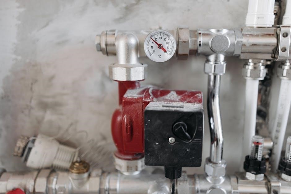
Ensuring Engine is Cold
Ensuring the engine is cold is a critical step in the valve adjustment process for the 6.7 Cummins engine. A cold engine ensures accurate valve lash measurements, as heat can expand metal components, leading to incorrect clearances. The engine should be allowed to sit for at least 30 minutes to an hour after shutdown to ensure proper cooling. The coolant temperature should be below 140°F for accurate readings. Never attempt to adjust valves on a warm or hot engine, as this can result in over-tightening or under-tightening of the valve lash, leading to poor engine performance or potential damage. Always verify the engine’s temperature before proceeding with the adjustment. This step is essential for maintaining precision and ensuring the longevity of your engine. Proper preparation and patience are key to a successful valve adjustment process.

Engine Positioning
Proper engine positioning is essential for accurate valve adjustment. Bring the engine to Top Dead Center (TDC) on cylinder one using an engine barring tool. Correct positioning ensures easy valve access and precise measurements.
Bringing the Engine to TDC
To bring the engine to Top Dead Center (TDC), start by rotating the crankshaft using an engine barring tool until the timing mark on the crankshaft gear aligns with the “0” mark on the timing cover. This ensures the piston in cylinder one is at the top of its compression stroke. Once the engine is in this position, the valves for cylinder one will be fully closed, allowing for accurate valve lash measurement. For the 6.7 Cummins engine, this step is critical for ensuring proper valve adjustment. Use a 15mm wrench to turn the crankshaft if an engine barring tool is unavailable. Always verify the position by checking the alignment of the timing mark before proceeding. This process ensures the engine is correctly positioned for precise adjustments and prevents errors in the valve lash measurement process.

Adjustment Procedure
The adjustment procedure involves using a feeler gauge to measure valve lash, loosening the adjusting nut, and turning the screw to achieve the specified clearance. Tighten the nut and recheck the clearance to ensure accuracy.
Sequential Valve Checking

Sequential valve checking ensures each valve is accurately adjusted in the correct order. Start with cylinder one, then proceed to cylinders three, five, and six for intake, and cylinders two, four, and six for exhaust. Use the engine’s firing order to guide the sequence, ensuring no valve is overlooked. This method prevents errors and maintains consistent engine performance. Always refer to the valve lash limit chart for exact specifications. Proper sequencing is crucial for maintaining engine balance and preventing damage. By following this structured approach, you ensure all valves are within the recommended clearance, optimizing engine efficiency and longevity.
Remember, sequential checking must be done methodically to avoid missing any valves, which could lead to uneven engine operation. Adhere strictly to the manufacturer’s guidelines for accurate results.
Using an Engine Barring Tool
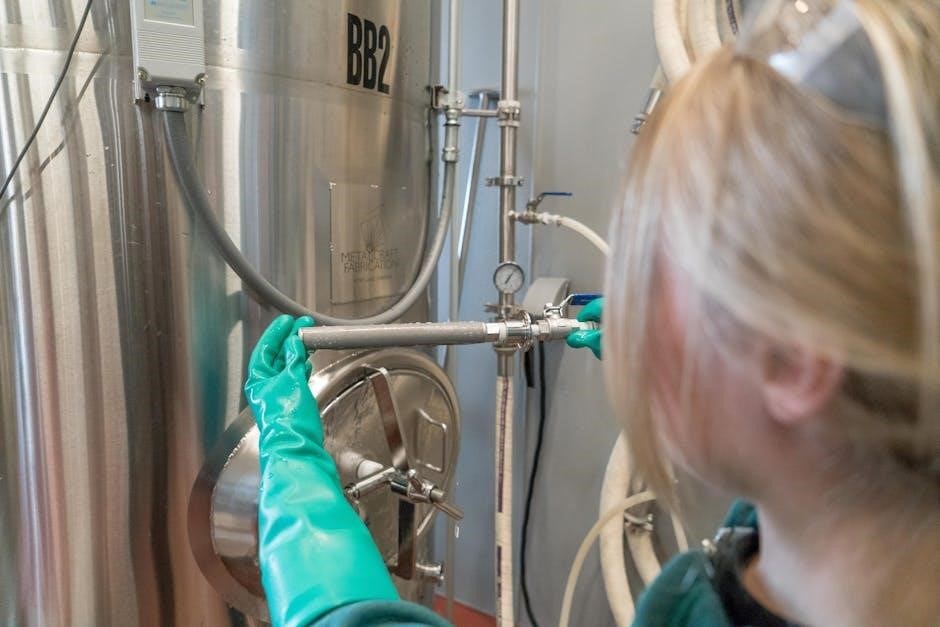
Using an engine barring tool is essential for safely and accurately positioning the crankshaft during valve adjustment; The tool is installed on the crankshaft and used to manually rotate the engine, allowing precise control over piston position. This ensures the valves are in the correct position for adjustment. The barring tool helps prevent engine damage by avoiding sudden or uncontrolled movement. Always use a wrench or socket to turn the tool, ensuring smooth rotation. After positioning the engine at TDC for the desired cylinder, remove the tool to proceed with adjustments. Proper use of the barring tool is critical for maintaining engine stability and achieving accurate valve lash measurements. Follow all safety guidelines when operating the tool to avoid injury or damage. This step is fundamental for ensuring the adjustment process is both effective and safe.
Never use the barring tool to start the engine; it is solely for positioning purposes.
Adjusting Valve Lash
Adjusting valve lash on the 6.7 Cummins engine requires precision to ensure proper engine performance. Once the engine is positioned correctly and valve lash measurements are taken, loosen the jam nut on the rocker arm with a wrench. Insert the appropriate feeler gauge between the rocker arm and valve stem to check clearance. Compare the measurement to the valve lash limit chart to determine if adjustment is needed. If adjustment is required, turn the adjusting screw clockwise or counterclockwise until the feeler gauge fits snugly. Tighten the jam nut securely to hold the adjustment in place. Repeat this process for all valves, ensuring each meets specifications. After adjustments, recheck the clearances to confirm accuracy. Proper valve lash adjustment ensures efficient engine operation, prevents premature wear, and maintains fuel efficiency. Always refer to the factory specifications for exact lash settings to avoid over-tightening or excessive clearance.
Accurate adjustments are critical to avoid engine damage and ensure optimal performance.

Post-Adjustment Steps
After adjusting the valve lash, recheck all clearances to ensure accuracy. Reinstall the valve cover and tighten bolts in the specified sequence. Perform a final inspection of all components and connections.
Ensure everything is secure before starting the engine to test performance.
Rechecking Clearance
After adjusting the valve lash, it is essential to recheck all clearances to ensure they meet the specified tolerances. Use a feeler gauge to verify intake and exhaust valve clearances, comparing them to the valve lash limit chart.
Ensure the engine is cold, as heat can affect measurements. For a 6.7 Cummins, typical specifications are 0.010” for intake valves and 0.026” for exhaust valves. Double-check each rocker arm to confirm proper adjustment.
If any clearance is outside the recommended range, repeat the adjustment process. Accuracy is critical to prevent engine damage or performance issues. Once all clearances are confirmed, proceed to reinstall the valve cover and other components. Rechecking ensures the adjustment process was successful and reliable. This step is vital for maintaining engine health and performance.

Reinstalling the Valve Cover
Once the valve lash adjustment is complete and clearances are confirmed, reinstall the valve cover to protect the engine components. Begin by ensuring the valve cover and engine surface are clean and free of debris.
Apply a new valve cover gasket, aligning it properly with the mating surface; Carefully place the valve cover onto the engine, ensuring it is seated evenly. Tighten the valve cover bolts in a star pattern to avoid warping the cover.
Refer to the service manual for the correct torque specifications. Once tightened, inspect the area for any signs of leaks. Reinstalling the valve cover completes the adjustment process, restoring engine integrity and protection.
Finally, start the engine and listen for any unusual noises or check for leaks around the valve cover. This ensures the reinstallation was done correctly and the engine is ready for normal operation.
Additional Resources
Consult the official Cummins QSB 6.7 service manual or download the PDF guide for detailed valve adjustment procedures. Watching instructional videos can also provide visual guidance for a clearer understanding of the process.
Consulting the PDF Guide and Service Manual
The official Cummins QSB 6.7 service manual provides comprehensive instructions for valve adjustment, including detailed specifications and step-by-step procedures. Downloading the PDF guide ensures access to accurate information, essential for maintaining engine performance. The manual covers pre-adjustment checks, tool requirements, and post-adjustment verification, ensuring a thorough understanding of the process. Referencing this document helps avoid common mistakes and ensures compliance with manufacturer recommendations. Additionally, the PDF guide includes diagrams and charts, such as the valve lash limit chart, which are crucial for precise measurements. By following the manual’s guidelines, you can perform the valve adjustment confidently and effectively, maintaining your engine’s optimal condition. Regular use of these resources ensures that your 6.7 Cummins engine operates within specified parameters, prolonging its lifespan and reliability.
Watching Instructional Videos
Instructional videos provide a visual and practical guide to performing the 6.7 Cummins valve adjustment. These videos demonstrate step-by-step procedures, making complex tasks easier to understand. They often include close-ups of tools like feeler gauges and engine barring tools, showing how to measure valve lash and adjust it accurately. Many videos cover essential steps such as bringing the engine to TDC, removing the valve cover, and using the correct specifications from the valve lash limit chart. Additionally, they may highlight common mistakes to avoid, ensuring a smooth process. Videos are particularly helpful for DIY enthusiasts or those less experienced with engine maintenance. By watching these tutorials, you can gain confidence in performing the adjustment correctly. They also serve as a useful supplement to the PDF guide, offering a real-world perspective on the procedure. Leveraging both written and visual resources ensures a thorough understanding of the 6.7 Cummins valve adjustment process.
Maintenance Schedule
Subsequent valve lash adjustments are recommended at 77,000 km (48,000 mi) intervals to maintain optimal engine performance and prevent potential damage. Adhering to this schedule ensures longevity and efficiency of your 6.7 Cummins engine.
Subsequent Adjustment Intervals
Regular valve lash adjustments are essential for maintaining the performance and longevity of your 6.7 Cummins engine. According to the service manual, subsequent adjustments should be performed every 77,000 kilometers (48,000 miles) to ensure proper engine operation. This interval is designed to prevent excessive wear on valve train components and maintain optimal engine efficiency. By adhering to this schedule, you can avoid costly repairs and ensure your engine runs smoothly over time. It’s important to follow the recommended intervals and use the specified tools and procedures to guarantee accurate adjustments. Proper maintenance will help extend the life of your engine and keep it running at peak performance levels.
Completing the 6.7 Cummins valve adjustment ensures proper engine function and longevity. Always adhere to specified clearances for optimal performance. Regular maintenance and accurate adjustments will keep your engine running smoothly for years to come.
Final Checklist
After completing the valve adjustment, ensure all steps are verified. Double-check valve lash measurements using the feeler gauge to confirm they match the specifications in the chart. Reinstall the valve cover securely to prevent leaks. Start the engine and listen for any unusual noises that might indicate an issue. Verify that all tools and materials are accounted for and properly stored. Review the maintenance schedule to plan for the next adjustment interval, typically every 48,000 miles. Ensure the engine is cold before driving to avoid any potential damage. Keep a record of the adjustments made for future reference. Finally, dispose of any used materials responsibly and clean the workspace thoroughly. A thorough final inspection ensures reliability and performance of your 6.7 Cummins engine.